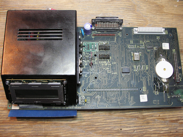

This Elan 5000 was donated to me as it was not working. When powered on it would create a little smoke and, if left on for a few seconds more, would blow the fuse. This was a little worrying but I still investigated the problem because so few of these programmers have survived and I thought that I would find out why. This particular one had a serial number of 50007 which I assumed was the seventh production unit built. The NiCad battery mounted on the PCB had leaked and possibly damaged some tracks so I removed it and cleaned up the area around it. There was a memory expansion card fitted with 256K SIPPs (remember those ?) mounted to the top of the board which I removed.
The unit has a single four layer PCB containing both a switch mode power supply and the microprocessor circuitry which I instantly thought was odd. In my experience, multilayer PCBs are not used for SMPs, probably because the high voltages present require isolation from other parts of the circuit and the material between the layers of a multilayer PCB could not provide this.
It was obvious looking at the power supply section where the problem was (there was a wire soldered across this before the picture was taken and replaced in a later picture) but why had the track burnt originally ?
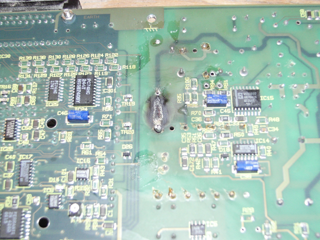
The track was the connection from the 370V DC +ve terminal of a pair of capacitors in series to one side of the transformer primary winding. The other side of the primary is connected to 0V. With the wire removed a resistance of approx 140 ohms could be measured between the +ve of the capacitor and 0V. This meant that the fuse would blow even if the wire was not replaced as there was a short across the capacitors. After some more measuring I discovered that the reading reduced if I pushed down on the burnt area meaning that the short was internal to the PCB. If the PCB was held up to the light it is possible to see the internal layers and the second layer came very close to the area where the track had melted and this layer was connected to 0V. I believe that, over time, the PCB material between the surface track, at 370V DC, and the second layer, at 0V, had broken down, heated up and burnt the PCB.
The only way I could see to fix this was to perform some minor surgery. Using a bladed knife I cut down into the PCB until I reached the track in the second layer and removed any pieces of metal and carbon which were still causing the short. There was very little metal but a lot of carbon and, eventually, the resistance reading rose to a few K ohm and after more brushing and cleaning to a few M ohm. I then refitted the wire across the burnt track area. For a permanent repair I would apply epoxy resin to the damaged area, first making sure though that it is non-conductive.
The two parts of the PCB, PSU and microprocessor are connected by some links which carry the power supplies. These were probably fitted at the factory only after each part was tested separately. So that I did not damage the microprocessor circuitry I removed the links and switched on. Success ! It stayed on and the outputs at the test points next to where the links were fitted measured -5V, 5V, 9V & 25V. The -5V & +5V are generated by 7805 and 79L05 regulators but I had no way of knowing if the 9V & 25V were correct. The capacitors for these supplies were rated at 16V & 25V so they seem ok as the +9V is also used as the input voltage for the 7805 regulator.
I reconnected the links and powered on again with no program cartridge or ZIFPAC fitted. The display showed dark blocks on the top line and the sounder made a horrible screeching sound. When I tried again with the program cartridge fitted the screeching became a continuous beep but still with no display. Time for a break !
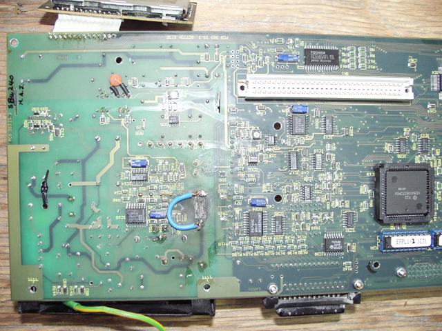
When I next had some time I returned to the Elan. The manual mentions that it checks the voltages at power on so it was possible that it was checking the NiCad battery voltage and failing as it was not fitted. I also had to check the tracks around the battery for damage and some time later I had found two broken tracks on the top of the board. These tracks were under the battery and had been eaten away.
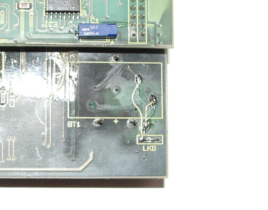
I soldered in some wires to replace the tracks, see above, fitted a NiMh battery and tried again with the program cartridge. Success, it came up with a display which said "Testing Ram" and then gave an error about not detecting Vpp I think. I didn't have that long to test it though as it died again soon after and only beeped on power on.
I think that I will need to recheck the tracks around the battery for damage when I have some time.
I had disconnected the NiMH battery after the previous tests. Two months later I switched the Elan 5000 on with the 145 ZIFPAC and it displayed "Testing Ram", "Installed 2048K" and "PLD ZIFPAC" "ISSUE EP 1-00" then "POWER OFF" "ISSUE EP 1.00". I turned it off and on a few times and it was doing the same each time until all it did was beep again. I guessed that this was something to do with the CMOS RAM used to store configuration and although there was a capacitor on the supply pin, with no battery connected, it was becoming corrupted when the voltage was out of spec. The voltage on the capacitor was 0.9V and would take some time to discharge so I discharged it with a resistor and now it would start up again. I knew that it performed a self-test at power on and the "POWER OFF" message may be because this self-test was failing.
When I changed to the 932 ZIFPAC the message was "Vcc OverCurrent Error(s)" and for the 187 ZIFPAC the message was "Error(s) Vcc OverCurrent" which leads me to believe that the problem now is the calibration of the current measurement.
Shown below are the signals present on the Elan 5000 program cartridge connector. This information will allow me to detect broken tracks on the PCB between the connector and the CPU. The cartridges use a 48 pin DIN41612 male connector with the following pin assignments, LNKIN and LNKOUT are connected on the PCB, all other signals are directly connected to the corresponding pin of the 27C010 EPROM except for D0 - D7 which are connected to the EPROM pin via a 56 ohm resistor.
There are two PCB versions.
The older version supports EPROMs up to the 27C010 and pin 30 of the EPROM is
connected to VCC pin 32.
The later version supports EPROMs up to the 27C020 and pin 30 of the EPROM is
connected to pin A7 of the 48 pin connector.
| Pin | A | B | C | ||
| 1 | GND | ||||
| 2 | LNKIN | LNKOUT | +5V | ||
| 3 | VPP | ||||
| 4 | |||||
| 5 | |||||
| 6 | PGM | OE (pin24) | |||
| 7 | A17 * | CE (pin22) | A16 | ||
| 8 | A15 | A14 | A13 | ||
| 9 | A12 | A11 | A10 | ||
| 10 | A9 | A8 | A7 | ||
| 11 | A6 | A5 | A4 | ||
| 12 | A3 | A2 | A1 | ||
| 13 | A0 | D7 | D6 | ||
| 14 | D5 | D4 | D3 | ||
| 15 | D2 | D1 | D0 | ||
| 16 | GND | GND | GND |
* Connected to EPROM pin30 on later PCB version only.
home contact