HP 2800 Business Inkjet PSU/formatter board repair
A common fault with this inkjet printer is the failure to power on. This particular
printer would flash the power light for a fraction of a second when the power
button was pressed but would not turn on. I was confident that if the case could
be removed to gain access to the PSU then I could repair it because if the light
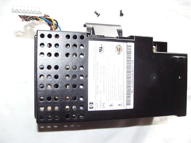
was coming on, even briefly, then it was not totally dead. The PSU is HP part
no. C8161-60031.
To repair the PSU will require knowledge of electronics repair, T10 and T20
Torx bits, a extended length T20 Torx bit and/or bit extension of total min
length approx 75-80mm to reach a recessed screw, jewellers and flat screwdrivers.
Update: 22/03/2014
A few months after I repaired the PSU the printer again failed to power on.
This time it would displays some moving dots on the display but after about
5 seconds it would turn off. I knew that it was very unlikely to be the PSU
again, so my attention turned to the formatter board. It is located on the left
side of the printer alongside the PSU.
Case and PSU removal
- Disconnect the power cable and parallel data cable and/or the JetDirect
(EIO) card.
- Remove the duplexer from the rear of the printer by pressing the two buttons
at the sides.
- Remove the memory expansion access cover using a coin to lever it open at
the rear, swing it out to the side and then slide it backwards.
- Remove the two short T20 head screws at the lower rear of the printer.
- Remove the two long T20 head screws at the upper rear of the printer.
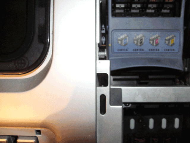
- Lift the ink/print head access cover and remove the recessed T20 head screw
on the left side located in the centre of the picture below. This screw requires
an extension and/or bit of min total length approx 75-80mm.
- Carefully lever off the trim around the front panel and remove the T10 head
screw on the left side.
- Slide both the side covers towards the rear until they can be removed.
- Insert a small screwdriver into each recess along the grey trim piece below
the front panel and lever it until it comes free.
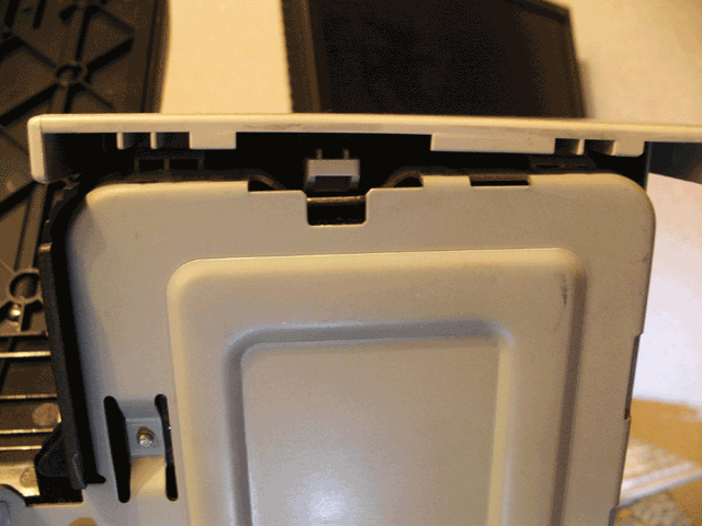
- On each side of the top cover at the front is a tab. On side at a time,
depress the tab while lifting the cover up, it may be easier to use a screwdriver
to do this.
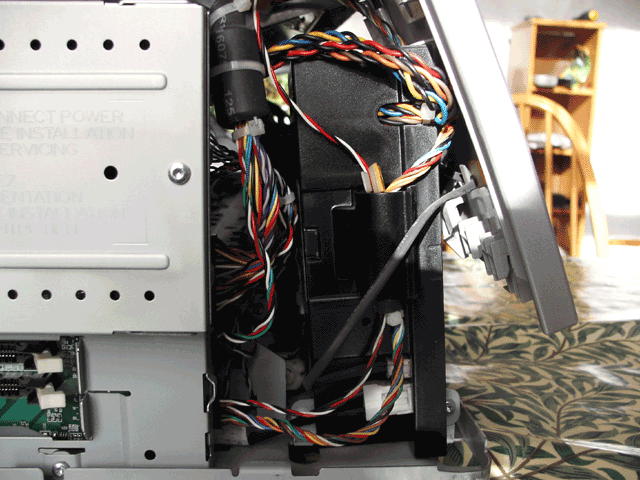
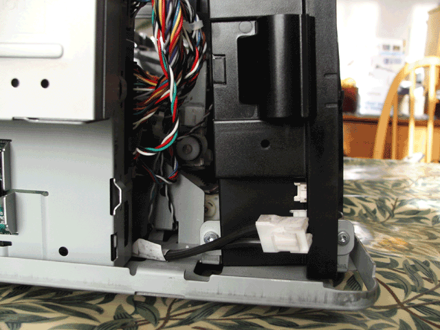
- The cover should now lift off but will be attached to the printer by two
cables. Disconnect the thinner cable at the connector to the PSU, disconnect
the larger cable at the connector to the logic board and prise out the ferrite
bead on the cable slightly from the clip on the side of the PSU, slide it
out and the cover can be removed completely.
- Disconnect the mains input connector to the PSU and the cable which plugs
into the logic board.
- Remove the two T20 head screws holding the PSU and then slide it out.
Please note that for safety reasons repairs to electronic equipment should
only be undertaken by a qualified electronics technician
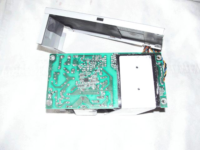
PSU repair
- Using a jewellers screwdriver lever out the small plastic pins from each
of the two clips in the PSU case. Once the pins are removed the clips can
lifted out.
- Insert a flat bladed screwdriver where the cover meets the metal base and
carefully lever the cover off.
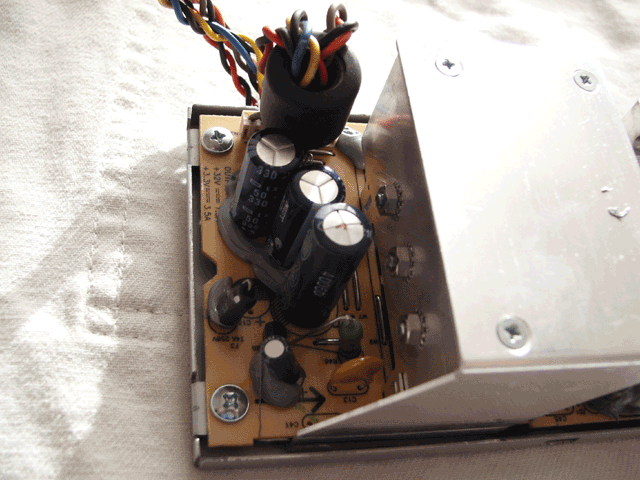
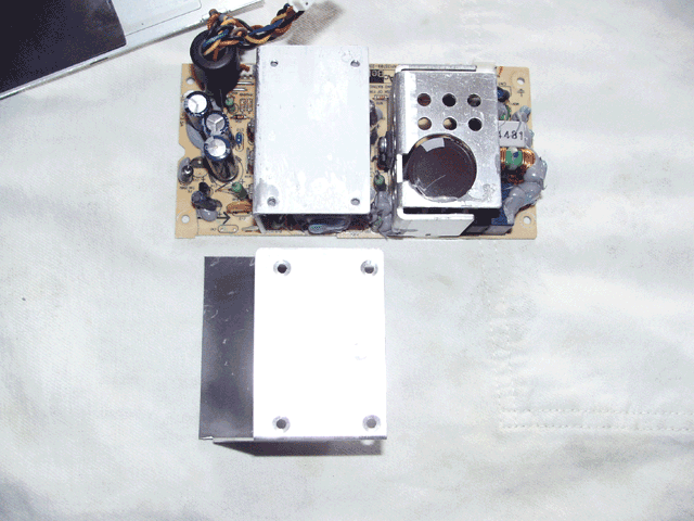
- The cause of the problem in this printer was the 4700uF 6.3V capacitor C14
on the 3.3V output used to power the logic. It had bulged at the top which
is a common failure and causes the voltage output to drop.The two 330uF 50V
capacitors used for the 33V outputs seemed ok but I changed them anyway. The
replacements should be low ESR types.
-
To gain access to the solder joints you will need to remove the four large
screws on the PCB and the two small screws underneath to remove the PCB.
Then you must remove the four small screws on the heatsink to remove the
metal heatsink and plastic shield.
Note: As the PCB tracks are very wide around these capacitors it will require
more heat than usual to melt the solder joints.
Formatter board removal
- Follow the instructions 1-11 above for Case and PSU removal
- Remove the T10 screw holding the cover for the EIO assembly and remove it.
- Remove the 4 x T10 screws holding the EIO connector PCB to the EIO assembly
and slide the PCB to the left to remove it.
- Pull out the EIO extender PCB from the formatter board.
- Remove the 3 x T10 screws holding the EIO assembly to the formatter board
assembly and slide it to the right to remove it.
- Remove the 3 x T10 screws holding the cover to the formatter board assembly
and remove it by pulling the left side forward and sliding it to the left.
- Unplug any connectors still attached to the formatter board.
- Pull the two flat black ribbon cables out of the connectors on the formatter
board.
- Using pliers remove the cable clip from the right side of the formatter
board assembly .
- Remove the T10 screw at the bottom left of the formatter board assembly,
slide it to the left and remove.
- Bend out the metal on the right side of the formatter board assembly slightly.
- Remove the 4 x T10 screws holding the formatter board onto the assembly
and carefully remove it by sliding it to the right and lifting out.
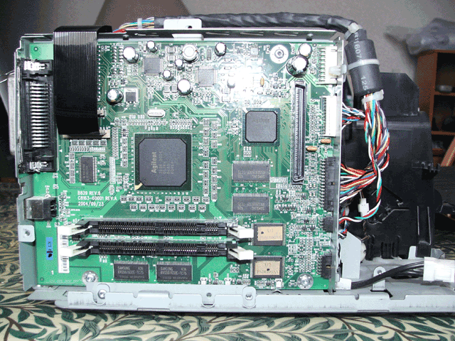
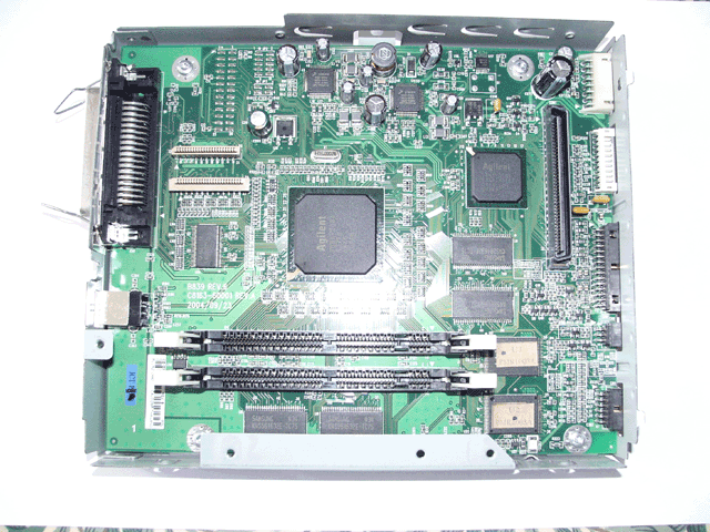
Formatter board repair
- On this PCB the 680uF 6.3V capacitor C265 was bulging and needed replacement.
This capacitor was one of many marked TEAPO and as these capacitors are particularly
prone to failure I decided to replace any so marked. These were C263,C265
680uF 6.3V and C122,C128,C133 & C141 10uF 50V, the replacements were low
ESR types.
After reassembling the printer it was working correctly once again.
Reassembly is the reverse of removal
home contact