HP Officejet 9130 ink supply station repair
This Officejet 9130 printer had been working correctly but a faulty magenta
cartridge leaked ink into the printer and after that the Cyan and Yellow cartridges
would no longer be detected. The message displayed was Magenta and Yellow ink
cartridges missing.
The scanner on this model makes case removal more difficult than for the HP2800
Business Inkjet and you will probably need someone to hold the scanner assembly
while it is being removed. This repair procedure will also apply to the 9110
and 9120 models.
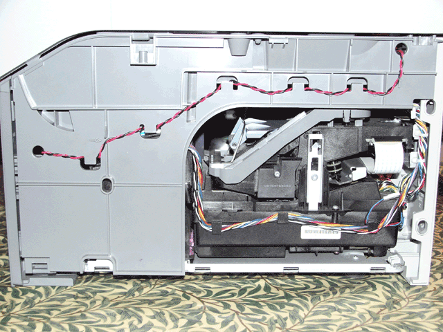
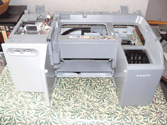
Case and PSU removal
- Disconnect the power cable and parallel data cable and, if fitted, remove
the JetDirect (EIO) card.
- Open the printer to access the ink cartridges (you will probably need to
prop it open with a piece of wood if the hydraulic strut is old), remove the
cartridges and lock the scanner mechanism using the sliding catch on the underside
of the scanner.
- Remove the duplexer from the rear of the printer by pressing the two buttons
at the sides.
- For each side panel, open the printer and remove the two T20 self-tapping
screws at the top the panel. Place the side of the printer at the edge of
a work surface, pull the top of each panel away from the printer until the
hooks at the bottom can be detached and remove it. (there are small clips
at the top and on both sides of the left panel so it takes a little effort
to do this side)
- Detach the two connectors on the PSU by pushing the clips on each and pulling
out, you will need to unhook the cable tie on one of the cables. Remove the
two T10 screws holding the PSU and slide it out, detach the connector at the
rear of the PSU and then remove it.
- Prise off the media card trim panel from the front of the printer.
- Open the printer and, while someone is supporting the scanner/panel assembly.
- Remove the two T10 screws holding the metal cover where the cables for
the scanner/panel assembly enter the printer base. Lift up the metal cover
on the right side to remove it.
- Detach the flexi pcb by carefully pulling it out of the connector and
then pull it through the ferrite.
- Remove two T20 self-tapping screws at the lower end of the supporting
strut, carefully lever plastic out using a small screwdriver and detach
it from printer base.
- Pull the scanner assembly back further than it would usually go to allow
access to the two long T20 screws at the top, near the hinges, and unscrew
them and then lift them out with long pliers.
- Using pliers, squeeze the two plastic clips on the ferrite beads and detach
them the metal screen. Detach the two connectors passing through the metal
screen.
- Remove the T10 screw holding the two earthing tags, the 34 way ribbon
cable connector and three smaller connectors.
- Remove the four T10 screws holding the metal screen.
- Using a small screwdriver through the media card access, carefully lift
the pcb to detach it from the main pcb below. Once it is loose, slide it
back and out. There will be two cables still connected to it for the scanner
assembly. The scanner/panel assembly and pcb can now be lifted away.
- Place the rear of the printer at the edge of a work surface. Remove the
two short T20 screws near the bottom of the rear panel. Lift the two clips
at the top of the rear panel and prise open the small clip on the top left
side which can be seen by looking up. Pull the top of the rear panel away
from the printer until the hooks at the bottom can be detached.
- Place the front of the printer at the edge of a work surface and lift the
rear of the plastic cover up until the hooks at the bottom front of the cover
can be detached.
Removal of side panels only
To gain limited access to the printer mechanism you only need to perform steps
1,2,3,4,7.1,7.2,7.3,7.4 & 8 above. In this case you will need someone to
be holding the scanner assembly vertical at step 8.

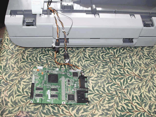
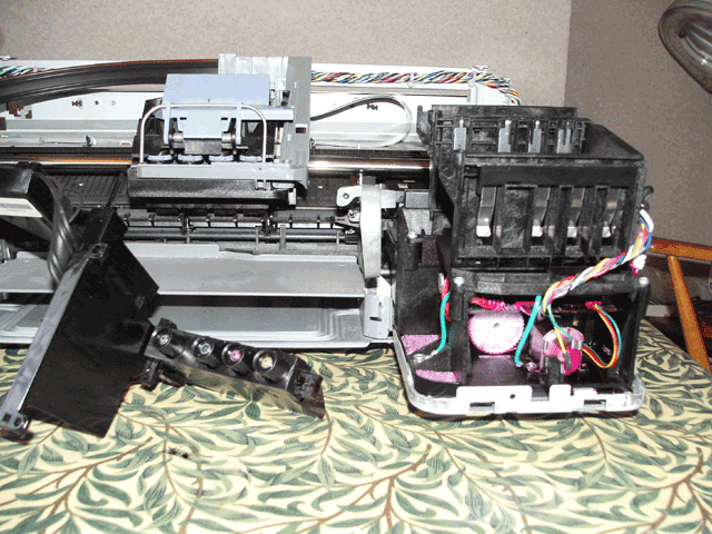
It was now obvious that magenta ink was covering most of the pcb in the ink
supply station below the cartridges. I assumed that this was causing the failure
to detect the Magenta and Yellow cartridges and that I needed to disassemble
the ink station.
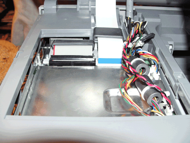
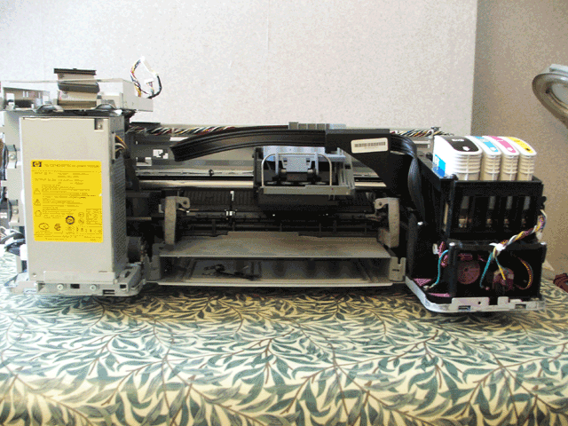
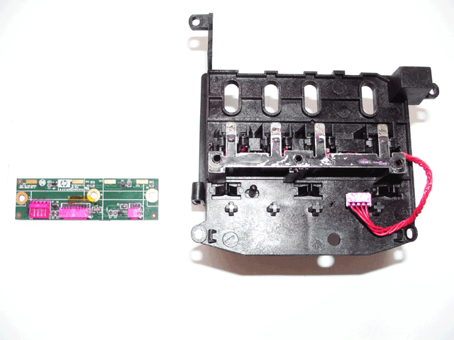
Ink supply station removal/disassembly
- Follow the instructions 1-9 above for Case and PSU removal
- Remove the two T10 black self-tapping screws holding the ink delivery system
to the supply station and remove it.
- Free the cables at the side of the station and printer from their clips,
start with the clips on the printer before those on the station.
- Using a small screwdriver, prise open the three v-shaped clips on the rear
panel of the station, one at a time, to allow the rear panel to lift out.
- Cut the cable tie at the front of the station, remove the four T10 screws
holding the supply station together.
- Unplug the two connectors on the right side of the PCB and lift off the
top of the supply station.
- Disconnect the last connector on the PCB, remove three T10 self-tapping
screws and lift off the PCB and metal contacts strip.
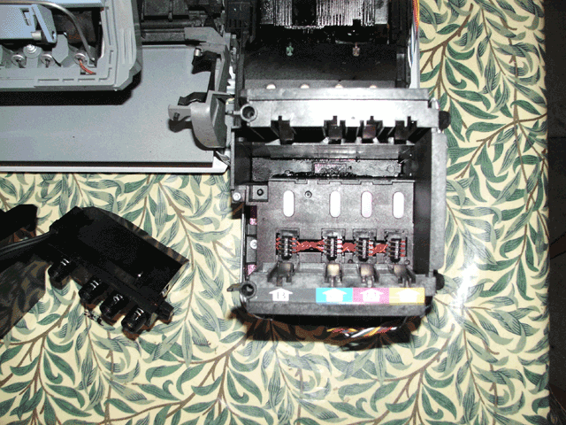
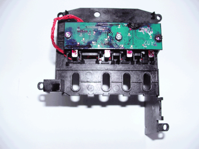
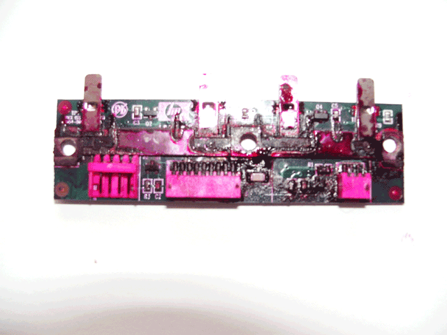
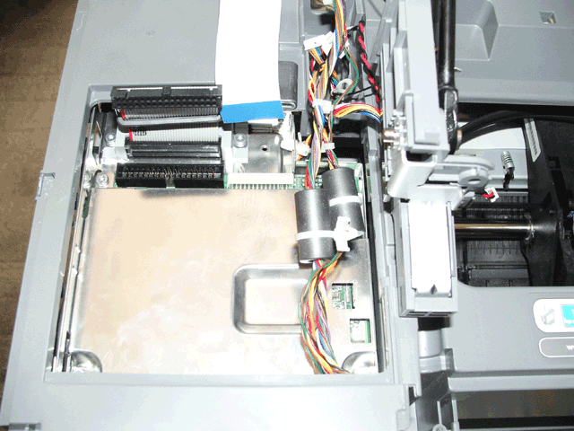
Ink supply station PCB C8154-80056 repair
The metal contacts strip acts as a simple switch so that when a cartridge is
missing the metal is lifted so that it does not make electrical contact with
the PCB. When a cartridge is installed the metal rests on a gold plated area
of the PCB, the strip is connected to the electronic circuit using the three
mounting screws. On this printer the PCB was covered with ink preventing the
Magenta and Yellow cartridges from being detected and needed to be cleaned.
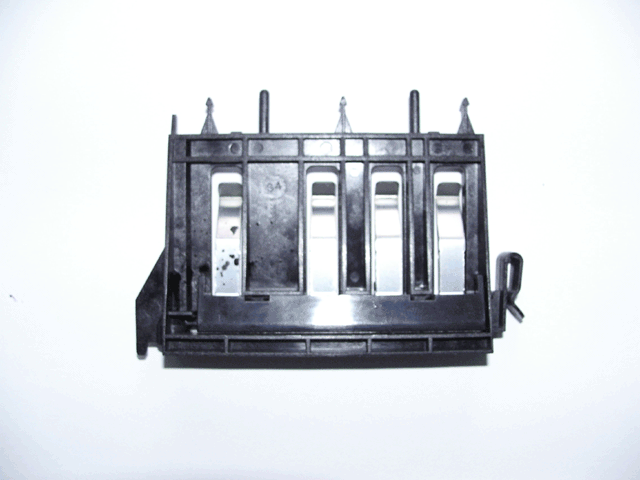
Take care not to damage the surface mounted components and be gentle. At first
I used Propanol but after having trouble removing the ink I used water to get
most of it off and then propanol and carefully dried the PCB and metal contacts.
Beneath the ink, the contacts were covered with a black substance and I assumed
that this was not ink but conductive paint and left it alone. When installing
the metal strip onto the plastic, engage the two end fixing holes first then
push down on the centre fixing hole. The last picture above shows the parts
after cleaning.
The ink on the PCB was indeed the cause of the fault and after reassembling
the printer it was working correctly once again.
Reassembly is the reverse of removal
Make sure that the connectors near the metal panel are secure after replacing
the supporting strut, that ears of the parallel connector at the rear are not
trapped by the rear panel and don't forget to unlock the scanner using the sliding
catch.
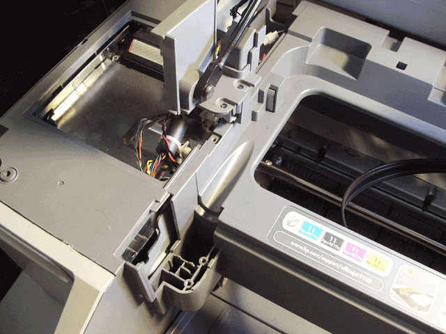
Update: 19/04/17
Recently the printer was displaying a "Door open. Close print-carriage
access door" warning when the access door was properly closed. Suspecting
a problem with the sensor at the rear I followed the "Removal of side panels"
instructions above to gain access to it as the sensor is high up at the rear
of the printer.
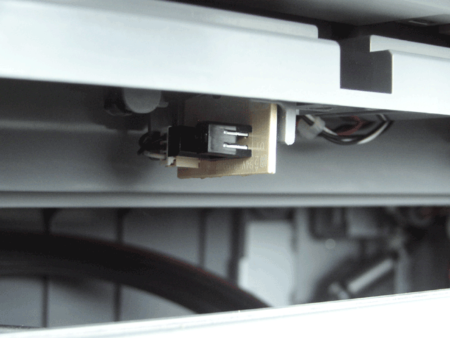
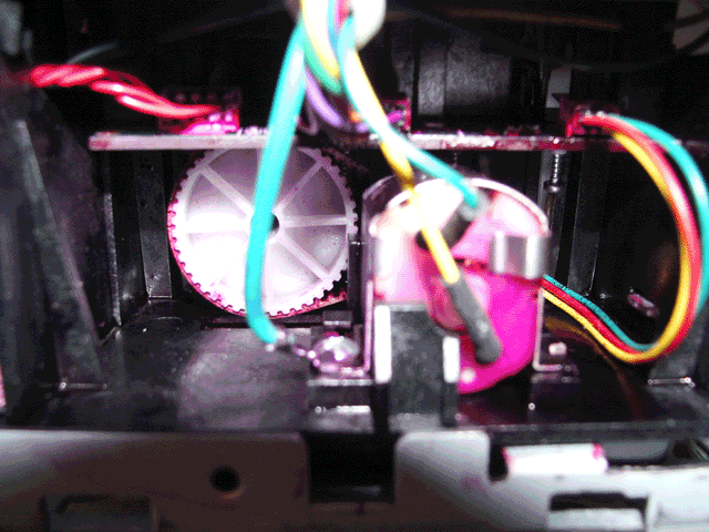
Initial checking of the sensor revealed nothing but I decided to check voltages
on each side of the optosensor on the small PCB with the printer powered up
but no voltage could be measured (I expected to measure something less than
5V DC). The most likely cause of this would be a bad connection between the
sensor and the main PCB so I traced the three wires back to a couple of white
connectors near the metal cover above the main PCB.
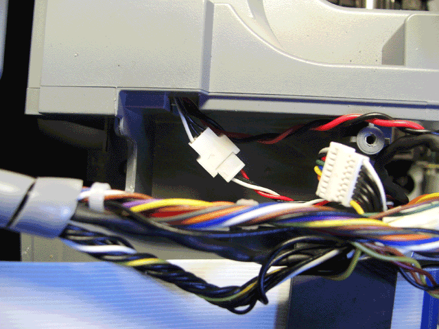
When I touched these they fell apart because there were not engaged correctly,
problem solved. This must have happened when the scanner assembly was originally
removed to fix the supply station problem since the the wires are barely long
enough to reach but if the scanner assembly if pulled back too far the connectors
may be loosened.
home contact