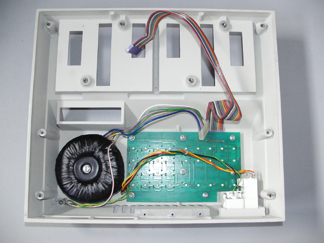
This L9000 was found on Ebay and when it arrived it was working correctly but, like all equipment over 20 years old, I assumed that I would need to change the electrolytic capacitors. I opened the case and found that there was a Varta 3.6V NiCd battery which had started to leak onto the PCB. The battery was removed by clipping the wire legs, the area around was cleaned up and the programmer re-assembled. I ordered replacement capacitors and a few days later, while I was still checking it, I left it on for a few moments and when I returned the keyboard was non-responsive. I switched it off and on but there was no display and the sounder was on continuously. I assumed that a capacitor had failed and when the replacements arrived I fitted them, however, when testing it the result was the same. The capacitors I removed were very leaky, the marked values were as follows,
but there must have been another fault, perhaps the PCB tracks around the battery had been damaged by the leak but why fail now and not before ?
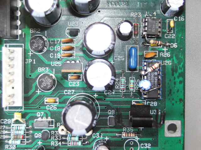
When working correctly the sounder will beep at power on, perhaps the CPU is not being reset correctly. First, I removed the sounder which is very loud and yes, the reset pin on the Z80H CPU was being held low and I assume that the CPU normally controls an I/O pin to turn the sounder off. After tracing the connection to the reset pin I found that it came from a 4528 dual monostable multivibrator labelled U26 on the PCB. The input which was supposed to trigger it was pin 4, which was always around 4.7V, and was connected to pin 4 of a 8 pin IC SL443A labelled U24, a 4V7 zener diode D6 and pin 6 of a PAL U38. U24 was near to where the battery leak had been and I changed the socket for U24 which had some corrosion and a 3.3nF timing capacitor had changed value slightly but I did not know if these were related to the problem or not.
The Plessey SL443A chip is a strange device which you would not expect to find in equipment such as this. It is intended to control mains powered heating elements by driving a triac directly using variable width pulses controlled by a potentiometer control knob. The control input is grounded to set the pulse width to the minimum value, the AC input is from C21 and R23 which is connected to a 13.8V AC output from the power supply transformer and the triac drive output is used to trigger the 4528. The maximum output voltage of the output is around 7V, it needs to be reduced to about 5V to drive the CMOS and TTL inputs and the zener diode is used for this purpose.
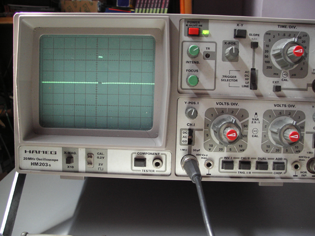
When tested the SL443A oscillated and generated the internal 7V correctly but the triac drive output never dropped to 0V as it should and so it seemed that the output circuitry had been damaged. This IC has been obsolete for some time but luckily I sourced a replacement from UTSOURCE. When comparing this to the original, it was possible to measure the 800 ohm drain resistor between pins 1 & 4 of the replacement but not on the faulty original. Just replacing the SL443A would fix the L9000 but considering how hard it is to find this IC I thought I should try to extend its life and reducing the output current using an external resistor would be a good idea to reduce the stress on the output circuitry when driving the output high. I lifted the leg of pin 4 up so that it was not in the socket and soldered a 100 ohm resistor between it and the cathode of the zener diode which gave a voltage drop of around 2V across the resistor when being driven. The oscilloscope display of the signal on the zener diode & U26 pin 4 is shown below, the width of the pulse is around 60 - 80 uS. While investigating this I noticed something odd about U26, considering that only half of the device was being used and it was CMOS, all the unused inputs of the other half were left floating. There were already some components soldered onto the IC and I added a piece of tinned copper wire to connect input pins 11,12 & 13 to 0V pin 8.
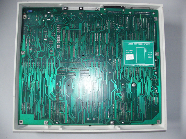
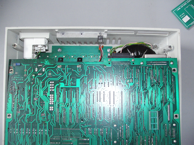
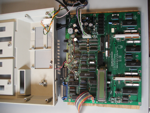
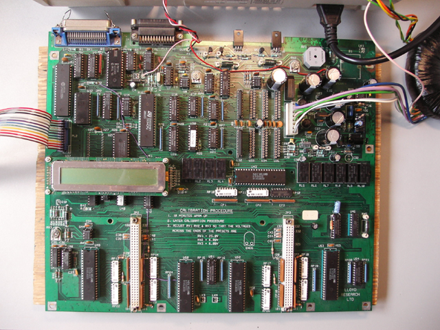
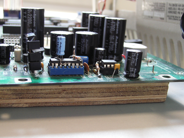
When disassembling the programmer you must remove the two screws securing the two BD647F transistors before removing the PCB from the case. There is also a 78S05 regulator fixed to the case and connected to the PCB by long wires. If the programmer is switched on this regulator must be fixed to the case as it gets VERY hot. It is normally mounted as shown in the third picture but for testing it was necessary to mount it as shown in the fifth picture to allow access to the component side of the PCB.
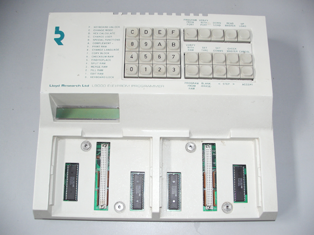
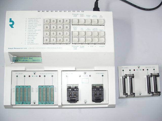
Now when it was switched on the monostable is triggered and the CPU comes out of reset correctly and I could replace the sounder. I reassembled it and it can be seen working in the last picture below.
For reference the outputs of the mains transformer are as follows
Green ----------- 13.8VAC
|
Pink ----------- 0V
|
Green ----------- 13.8VAC
Mauve ----------
| 10.6VAC
Blue ----------
Grey ----------
| 31VAC
White ----------
The L9000 is a bit quirky and as one example of this, although it was built in the UK, if the NiCd battery is disconnected the default language is set to French at power on !
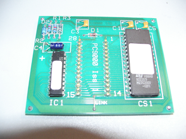
The firmware on this L9000 is located on a small PCB which plugs into a 28 pin socket on the non-component side of the main PCB. The PC9000, known as the update module, allows a 32 pin EPROM to be accessed in pages using a PALCE16V8Q-25PC/4 IC. The manual has a note in the "Updating programmer software" chapter about returning the original old EPROM as they can no longer be purchased so I assume that the update module is emulating a 27C011 EPROM.