Although I could have desoldered the EPROMs from each module and dumped the contents using an EPROM programmer this would have taken a lot of time and risked damage to the PCBs. Instead, the EPROMs could be accessed in the same way that the FLT does, through the 25 way D-Type connector.
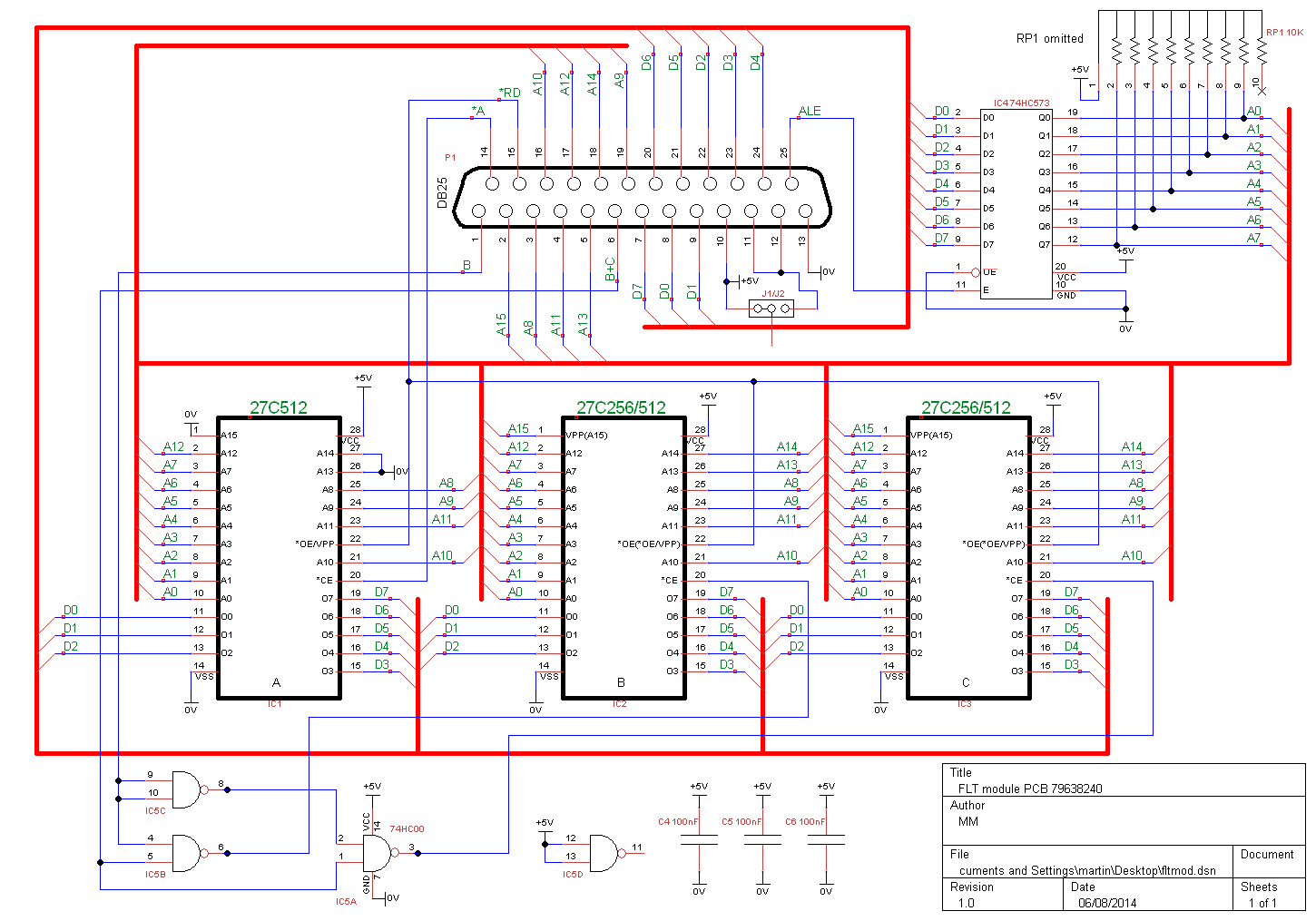
There are two main types of module PCB which differ in the size of the leftmost EPROM, 27C64 or 27C512, but they are both accessed in the same way. The lower 8 bits of the address are multiplexed with the data which reduces the number of pins required in the connector. A signal on pin 25 of the connector indicates when the address is present on these shared pins and is used to store this for later use.
Module PCB type 1 circuit diagram
Module PCB type 2 circuit diagram
I used an Atmel ATmega 8515 microcontroller which has an external memory interface with a multiplexed address/data bus as used by the FLT modules. The program loaded into the microcontroller was written in C and initially displays a menu on the serial port connection. Selecting Dump causes the EPROM contents to be read and transmitted in Intel hex format back to the serial port.
There is a slight problem if the module reader must dump the module contents when it does not know the EPROM types fitted. Either 27C256 or 27C512 devices can be fitted for the other two EPROMs and the A15 signal (the MSB of the EPROM's address) can only be driven low if 27C512 devices are fitted. For 27C256 devices this pin is the programming voltage and is normally held close to +5V by the device itself if a voltage higher than that is not applied.
The EPROM type detection is as follows. The A15 signal is not driven by this memory interface but instead by a general purpose pin that is configured initially as an analog input pulled down by a 10M resistor. Another pin configured as an analog input is supplied with a voltage of 2.5V and the two analog inputs are compared. If 27C256 devices are fitted the A15 signal will be pulled up to +5V and the A15 input will be higher that the fixed input. If 27C512 devices are fitted the A15 signal will be an address input to the EPROM and so pulled down to 0V by the 10M resistor and the A15 input will be lower that the fixed input. The A15 signal is then configured as a digital output and driven high for 27C256 devices or low for 27C512 devices.
home contact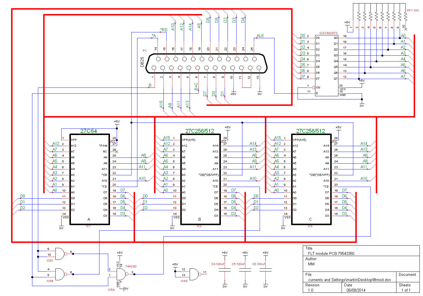