The Oxford Semiconductor OXPCIe952 has multiple modes which are selected by providing the correct voltages to the mode select pins. Some PCIe cards which use this chip allow the mode to be configured using jumpers which can connect each mode select pin to either 0V or 3.3V, however, other cards have the mode fixed at the factory using SMD resistors. Please refer to the OXPCIe952 datasheet which describes the possible modes and the device IDs for each function of a mode.
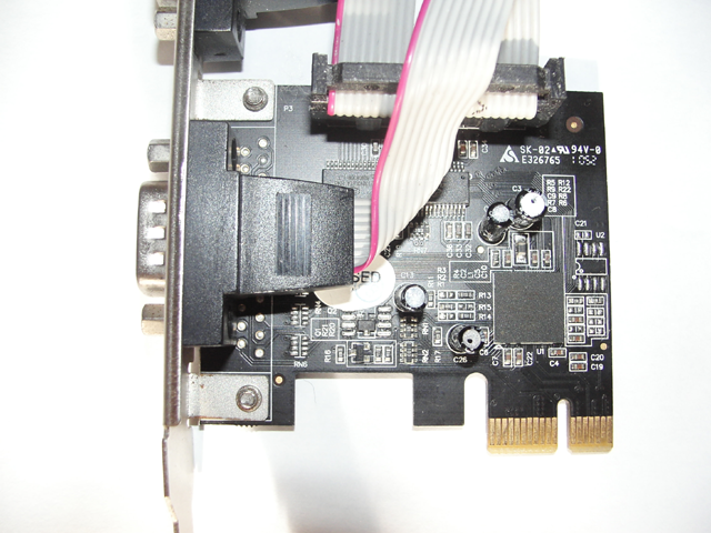
I obtained a PCIe dual serial card fitted with a OXPCIe952 and marked PI40952-3X2B on the back. I intended to use this with FreeDOS but, unfortunately, the mode of my card was set to 5 which configured the serial ports as "Native" UARTs instead of "Legacy" UARTs with device IDs of 0xC158 & 0xC159. "Native" UARTs are mapped into memory space whereas "Legacy" UARTs are mapped into I/O space. Modern CPUs and operating systems can access memory space many times faster than I/O space so there is a performance advantage for "Native" mode. DOS programs expect serial ports to be accessible using I/O instructions and so the mode of the OXPCIe952 needed to be changed to 4 with device IDs of 0xC140 & 0xC141.
A quick search for similar cards on the internet found someone with a parallel card using the same pcb as mine and sold as a StarTech PEX1P. They had posted a picture of their card and by comparing components I could determine which resistors selected the mode and what needed to be changed.
| Mode bits | Logic "0" | Logic "1" | Enable bits | Logic "0" | Logic "1" | |
| M2 | R3 | R13 | UART_EN | R22 | R12 | |
| M1 | R2 | R15 | GPIO_EN | R5 | R9 | |
| M0 | R1 | R14 |
The mode bits and enable bits are set by either fitting a 10K pull-down resistor
to 0V or a 10K pull-up resistor to 3.3V, M2 is the MSB and M0 the LSB of the
mode value. The dual serial card as supplied had resistors R13, R2 & R14
fitted so that the mode, in binary was 101 which is 5 in decimal. It also had
R5 & R12 fitted which enable the UARTs and disable the GPIO function. To
set the mode to 4, 100 in binary, would need resistors R13, R2 & R1 fitted
so I needed to desolder R14 and solder it in position R1, the UART and GPIO
enable resistors could be left as they were.
This is the card as supplied in mode 5 and after modification in mode 4
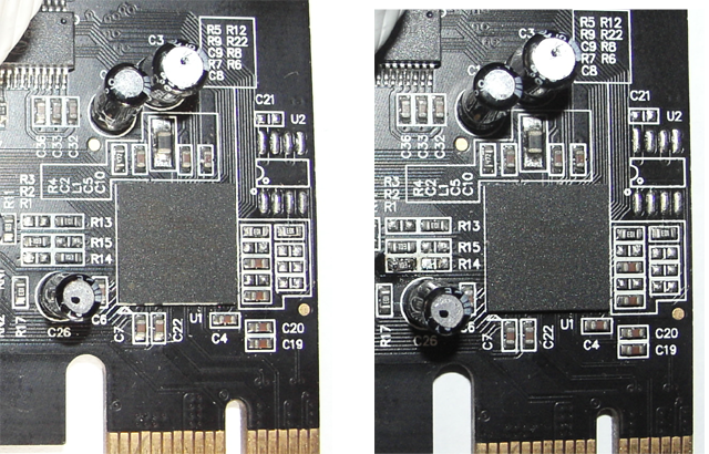
My soldering for R1 could have been better but at the time I was more interested in testing the card.
The Windows drivers used when configured as "Legacy" UARTs are different to those used when configured as "Native" UARTs. The official Oxford Semiconductor/PLX drivers for Windows has a folder named "Serial Port Driver" containing the "Legacy" driver and multiple folders for Windows versions containing the "Native" driver which I have made available here.
The Linux drivers for both "Legacy" and "Native" UARTs are built into the Linux kernel.
My card does not have the optional EEPROM U2 fitted. If it were fitted it is very likely that the PCI vendor ID would be changed from that of 0x1415 for Oxford Semiconductor to the card manufacturer's ID and their own drivers would be required. In this case, I do not advise making the modification because the card manufacturer's driver may not support "Legacy" UARTs with Windows or Linux.
home contact