The Stag PPZ, PP38, PP39, PP41 & PP42 programmers were produced from the early 1980s until the mid 1990s and had the ability to be controlled remotely by a PC. The optional Stag StagCom 1 software to allow this requires MS-DOS and the latest known version, 8.x, uses the Borland Turbo Vision library to implement a Text-based User Interface using windows and pull down menus on a 80 x 25 screen. As common with software of that time, it was designed to use the CPU exclusively and will not multitask very well on Windows 95 & 98 without some extra configuration. Although the serial communication will work after doing this for Windows 95 & 98, with later versions of Windows able to run it in a NTVDM window, the parallel communication does not work reliably and will not even work on MS-DOS if the PC has a CPU better than a 80486, presumably because the parallel port code uses timing loops. It should be mentioned that the parallel protocol on the Stag PP42 is not compatible with IEEE 1284 as the pins are driven in a unique way to provide bidirectional data transfer.
So that I could read and program EPROMs for another project I acquired a Stag PP42 which had a serial interface and the optional parallel interface. Unfortunately for me, only the parallel interface worked and, thanks to Matthieu Benoit and his PP42 page , I obtained a copy of StagCom 1 to control it in remote mode. After some testing I found that I could only use the software with my PP42 if it was running on a 80486 based PC. So I decided to investigate the Stag parallel protocol hoping that I could implement a simple file transfer program which could run on a more modern PC even if it was still running MS-DOS.
Even using a logic analyser the parallel protocol was difficult to figure out and it took a few months before I had something that could communicate with the PP42 correctly. So that it could work on hardware faster than a 486 based PC it needed to calibrate some timing loops using the execution time for an I/O instruction accessing the registers of the parallel port. This works because I/O instructions are not cached and so the access time will remain reasonably constant. The first version of the program was script based which allowed me to run test scripts for the various programmer functions.
Once I had a working program I realised that it could be useful to anyone with a Stag programmer as it allowed file transfer to be performed from a batch file. It would need to support the serial protocol as well and I, wrongly, assumed that adding code to do this would be much easier. Although my serial interface did not work, I could be sure that the commands were being formatted correctly and so I asked Matthieu Benoit to test it on his PP39, which shouldn't be that different to the PP42 as StagCom 1 had supported both.
The programmers do not all use the same type of microprocessor, the PPZ, PP41 & PP42 are 6809 based whereas the PP38 & PP39 are Z80 based and, as I believed that the firmware was written in assembly language, it is likely that the code for the two families differs in functionality. (I later discovered from an ex-Stag employee that the PPZ and the PP41 & PP42 do not share the same source) Over the next few months I found many protocol differences between the two families and several firmware bugs. Later I was also able to obtain another PP42 with a working serial interface which made testing easier. Initially, the program ran on MS-DOS just like StagCom 1 but I later created Windows and Linux console versions.
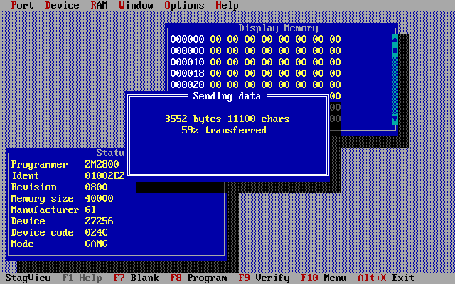
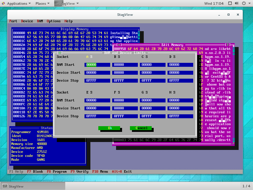
It had taken much longer than expected to create a working program but I had a library of all the necessary functions and it seemed sensible to take it a little further to create an application to provide the features of StagCom 1 but with the bug fixes and support for each of the MS-DOS, WIN32 & Linux platforms. The Turbo Vision library that Stag had used in the 1990s still looked good and some work had been done in around 2003 to port the library from MS-DOS to Unix/Linux and later to Windows. I chose to use this library as it gave a retro feel to the application, looking similar to StagCom 1 but with several improvements such as auto-detection of programmer/module and memory size, checking of data files for corruption for both send and receive and more responsive display/edit windows.
| Platform | Version | Required library |
| MS-DOS, FreeDOS, DOSBox-X, DOSBox (see Notes) | STG.EXE | |
| Win95,Win98,WinME,Windows NT,Windows 2000,Windows XP,Windows Vista,Windows 7 (32 bit) | STG32.EXE (or STG.EXE) | |
| Windows XP,Windows Vista,Windows 7 (64 bit) | STG32.EXE | |
| RHEL/CentOS 4.x-6.x Ubuntu/Linux Mint 17.x-19.x Suse 9.x-13.x (i386/i686 glibc 2.3.4) | stg (32 bit) | librhtv.so.2.0.3, (libstdc++.so.6) |
| RHEL/CentOS 4.x-7.x Ubuntu/Linux Mint 17.x-19.x (x86_64 glibc 2.3.4) | stg (64 bit) | librhtv.so.2.0.3, (libgpm.so.1) |
| RHEL/CentOS/Rocky 8.x-> Ubuntu/Linux Mint 20.x-> (x86_64 glibc 2.28) | stg (64 bit) | librhtv.so.2.2.3 |
Notes:
Running STG.EXE (or StagCOM) on DOSBox or DOSBox-X will require the .conf file
to be edited as follows.
In the [serial] section change the line for "serial1" to "serial1=directserial
realport:ttyS0 irq:4" for Linux hosts and "serial1=directserial realport:COM1
irq:4" for Windows hosts.
For Linux hosts the permissions for serial port access will need to be checked
using the seracctst.sh script as for a Linux install.
When STG.EXE is run windowed on Win95/98 you will need to create a shortcut to STG.EXE and in "Properties/Misc" set "Idle sensitivity" to Low.
For the 32 bit Windows platforms Win95,Win98,WinME,Windows NT,Windows 2000,Windows XP, Windows Vista & Windows 7 it is strongly recommended that STG32.EXE is used, running the 16 bit version STG.EXE adds extra overhead and program operation may be affected.
For the Linux platforms you will need to install the librhtv.so.2.0.3 or librhtv.so.2.2.3 library included in the .zip file if it is not already installed. The libstdc++.so.6 and libgpm.so.1 libraries may also need installing depending on the Linux distribution.
STG.EXE on FreeDOS
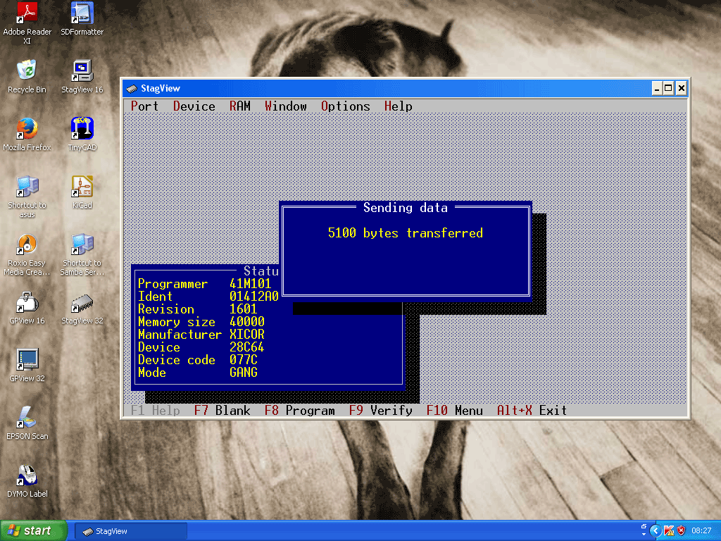
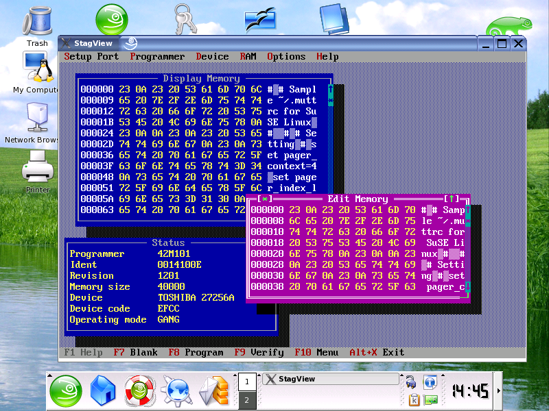
STG.EXE on Windows 98, STG32.EXE on Windows XP, stg (32 bit) on SUSE Linux 9.1, stg (64 bit) on CentOS 7.2
The application has been tested against the following programmers and modules. Each module will have many firmware revisions and I do not know if the software works with other firmware versions of these modules, please tell me if it does (or doesn't) using the contact link at the bottom of this page.
Please note the suffix 'A' for a module denotes that improved ZIF sockets are fitted which allow the use of 'skinny DIP' devices. Such a module is otherwise identical to the older type without the suffix and the firmware is interchangable.
| Programmer | Module | Revisions |
| PP38 | PP38M | 1.0 |
| PP39 | 39M100 | 9.3,12.0,13.0,17.4,18.2,18.4 |
| 39M101 | 3.1,6.1,8.1,9.0,12.0,17.5 | |
| 39M200 | 2.0,4.0,7.0,8.0,10.0,14.0 | |
| PP41/42 | 41M100 | 5.0,8.0,11.0,12.0,13.0 |
| 41M101 | 4.0,7.0,14.0,16.1,17.1 | |
| 41M102 | 3.0,14.1 | |
| 41M200 | 3.0,12.0 | |
| 42M101 | 12.1,13.1,16.1,19.1 | |
| PPZ/System 3000 | ZM2000 | 26.0,30.1,32.2,35.0,37.0,39.0 |
| ZM2500 | 8.1,11.0 | |
| ZM2800 | 8.3 |
It should work with the following supported programmers and modules but this has not been tested.
If you have tried the software with any of these please contact me to let me know the result.
| Programmer | Module |
| PP41/42 | 41M103 |
| 41M111 | |
| 41M121 | |
| 42M100 |
1) The parallel protocol is only supported by STG.EXE running on MS-DOS or WIN95/98 in MS-DOS mode. This is because of the critical timing required which can only be met if the program has exclusive access to the PC hardware. The rate of transfer in parallel mode is roughly twice the rate when in serial mode at 38400 baud. If there is a parallel port on the PC motherboard it should be configured in the BIOS to 'Standard', 'Normal' or 'SPP' mode which duplicates the type of port found on the original IBM PC. If it does not work then try 'Bi-directional' or 'PS2' then 'ECP' or 'ECP+EPP'. For more information on which parallel ports are compatible with StagView and StagCom1 see this page Serial/Parallel port compatibility. The parallel port PCI cards commonly available can be used with MS-DOS and the PrtAdd program, see below for more information.
2) For the serial protocol, baud rates up to 19200 for the PP39 and PPZ or 38400 for the PP42 should work on all platforms. StagView will work at these speeds with handshaking set to 'None' because it adds delays to the data stream for file input to the programmer when connected at the fastest baud rate. Handshaking is only used by the programmer during file input and output at the highest baud rate and I have found the implementation to be seriously flawed so the only available handshaking option now is 'None'.
(Almost all PCs have serial interfaces with 16C550 UARTs and they have no problem receiving data at high baud rates for file output. For file input the small buffer size in the programmer means that when the handshaking signal, hardware or XON/XOFF, is sent to the PC it must immediately stop sending data otherwise the programmer buffer will overflow and data will be lost. When the handshaking signal is received the 16C550 will empty the contents of the transmit FIFO before transmission is stopped. Adding delays to the data stream allows the transmit FIFO to empty and then the programmer can process the data and empty its buffer)
3) It is possible to use a commonly available DB9F (or DB25F) to DB25M null modem cable. However using one with a PP3X or PP4X programmer, a release earlier than 1.7 and DOSBox or DOSBox-X will cause DOSBox/DOSBox-X to hang. Since release 1.7 null modem cables can be used with all supported platforms.
The minimum cable connections required are shown below if not using a ready-made null modem cable.
| Programmer end | PC serial port end |
| 25 way male | 25 way female |
| pin 1 PG connect to cable shield | n/c |
| pin 2 TXD | pin 3 RXD |
| pin 3 RXD | pin 2 TXD |
| pin 7 SG | pin 7 SG |
or
| Programmer end | PC serial port end |
| 25 way male | 9 way female |
| pin 1 PG connect to cable shield | n/c |
| pin 2 TXD | pin 2 RXD |
| pin 3 RXD | pin 3 TXD |
| pin 7 SG | pin 5 SG |
Note
a) The cable shielding, if present, should be connected to pin 1 at the programmer end. The cable diagram supplied by Stag used the Protective Ground as the Signal Ground to simplify the wiring. However, when the 9 pin PS/2 serial port became standard there was no pin for Protective Ground on the 9 way connector so Signal Ground must be connected at both ends instead.
Now that I have been able to test many versions of module firmware, the database which generates the SUPPORT.DAT file covers enough module types to create a master device support list. The current version shows device codes and, if known, the firmware versions supporting the device for all the supported programmers and modules. Stag, like manufacturers do today, added aliases to the xxxxxx.DAT file for devices which may only differ in the packaging. I have added these to the SUPPORT.DAT file and as a result they will appear in this list. If I had time I would check them and only add them if they were significantly different. The document can be accessed using this link Stag Device Support List. The list of latest firmware versions for Stag PP4X programmers and modules can be found here.
The previous releases of the MS-DOS version STG.EXE were only able to use serial and parallel ports which had been detected by the PC BIOS at initialisation. The i/o addresses of these ports can only be 3f8,2f8,3e8 or 2e8 for COM1-4 and 378,278 or 3bc for LPT1-3. These are the legacy addresses assigned by IBM for the original PC and each has a corresponding default irq no. e.g. 3f8 uses irq 4. The BIOS saves the address for each port detected in a BIOS table in memory which defines the port to be used for each serial and parallel MS-DOS device name. The names for the physical ports are normally assigned in the order that the legacy ports are detected i.e. the first serial port detected may not be at address 3f8 but 2f8 instead and so COM1 could be assigned to address 2f8 with irq 3.
PCI/PCIe serial and parallel cards are assigned i/o addresses and irq no.s at initialisation by the Plug and Play BIOS which do not correspond to the legacy addresses and irq no.s above. MS-DOS programs are normally unable to determine the address and irq no.for a port on a PCI/PCIe card as the address is not stored in the BIOS table in memory and the irq no. could be any value.
So that non-legacy port addresses can be used I have written the PrtAdd program to scan the PCI bus, discover the serial and parallel ports on any cards that it supports and save the addresses and irq no.s so that StagView, can access them. The current release of StagView together with PrtAdd is able to use serial and parallel ports on PCI or PCIe cards. This allows the creation of BBBD, a FreeDOS bootdisk containing StagView and usable on a modern PC which may not have any legacy ports at all on the motherboard.
It should be possible to use a USB-Serial cable to connect the PC to the programmer
when using STG32.EXE or stg.
I have performed some tests with StagView using such devices and the results
can be seen here.
Download the zip file containing executables for MS-DOS, WIN32 console and Linux (32 & 64 bit).
![]() stg1.8.1.zip
18/04/24
stg1.8.1.zip
18/04/24
Alternatively, StagView for MS-DOS can be run from the BBBD iso without installation.
1. Check port settings
a) for PPZ
Use on-screen menus to view/change settings. If the display is not functioning you can follow the instructions here.
b) PP39,PP42
Press "SET 1" on the programmer to change/view port settings, "LEFT" or "RIGHT" to select a parameter and "UP" or "DOWN" to change and "EXIT" to finish. If programmer does not respond then turn it off and turn it on while pressing "EXIT" then try again.
2. Enter remote mode
a) for PPZ
Insert the mode key and turn it to position 3 (fully clockwise) and press the "RESET" key.
b) PP39,PP42 etc
Press "SET 2", ("UP" or "DOWN" to change port for models with more than one port) and "SET" to finish.
3. Start the StagView executable and connect with the programmer
Select the "Port" menu and "Connect" option. Ensure that the settings are the same as those on the programmer and select "OK". There will be a delay while StagView determines the programmer type and configuration.
(Some of these apply to StagCom too)
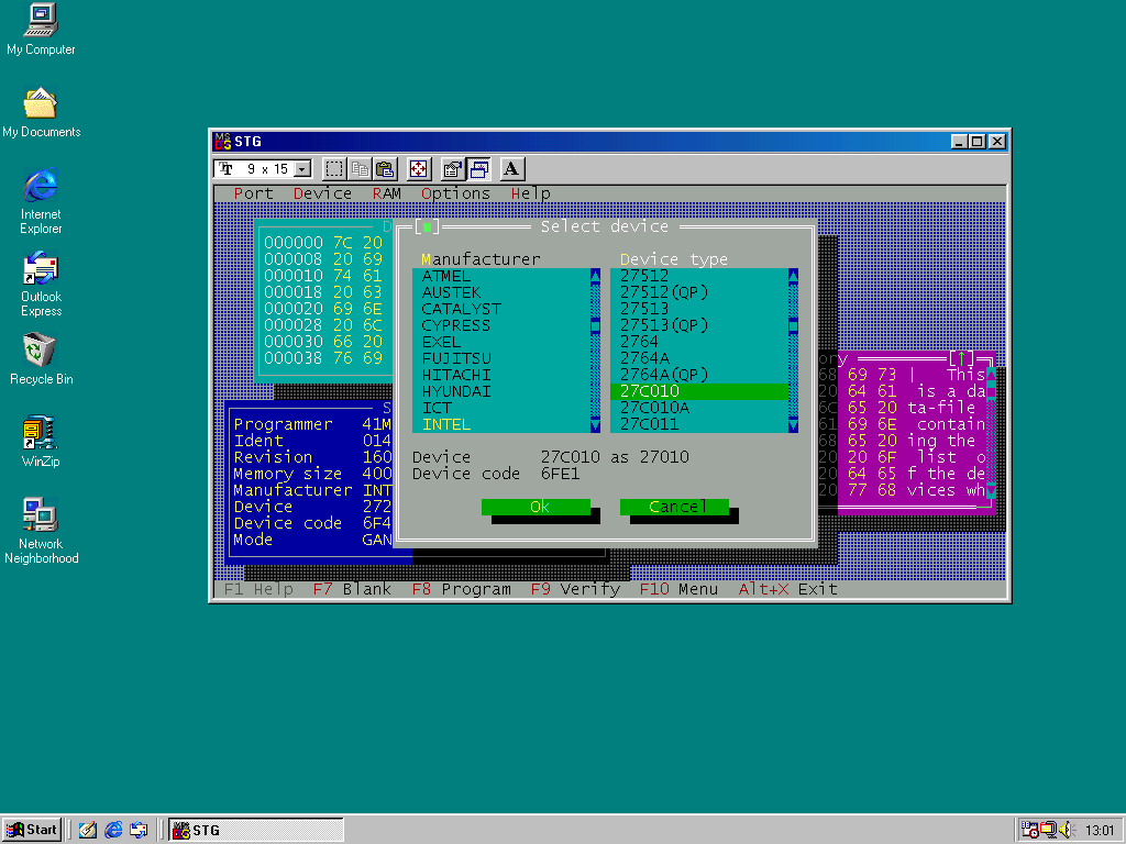
It is currently possible to see devices in the "Select Device" dialog box which are not supported by the current firmware revision if the xxxxxx.DAT file, where xxxxxx is the programmer/module name, is for a newer revision. However, if one of these is selected it will not be possible to confirm the change using the OK button and you should either change the selection to a supported device or use Cancel. Also, if the programmer firmware is later than the contents of the xxxxxx.DAT file some devices will be missing from the dialog box. As more firmware versions are discovered then the xxxxxx.DAT and SUPPORT.DAT can be updated.
There is currently no help facility in the application.
The MS-DOS STG.EXE has a minimum step size when scrolling the Display/Edit window which is not present in the WIN32 and Linux versions. This is caused by the limitations of the Turbo Vision library for MS-DOS.
The statistics and serialisation functions of StagCom are not present in StagView. I felt that the extra work to implement these would be a waste of time considering that these were meant for use in a production environment and I doubt that anyone would still be using them for this purpose. I could be wrong.
Be aware that the PP39, as a result of firmware bugs and the lack of error checking for some commands in remote mode, will take around 20 seconds at 9600 baud to complete the initial connection phase while the memory size and module type are determined.
There may be other issues purely because of the different possible combinations of programmer/module/firmware revision
There is a serious problem when using StagCom1 with the PP38 or the PP39 with the 39M100 or 39M200 module which may cause device damage or failure to program reliably. This is caused primarily by the PP38 and PP39/39M100/39M200 responding to the "Set Device" command incorrectly if the device code is not supported, either because the xxxxxx.DAT file is newer than the module firmware or there is a typing error in the file. StagCom1 assumes that if the response is "accepted" the programmer has set the current device to that requested and it displays this device type on the screen. Unfortunately, the programmer has left the current device unchanged and, if the previous device had the same pinout as the selected device, it may use incorrect programming parameters for the devices in the sockets. StagView, when used with the PP38 or PP39/39M100/39M200, always verifies that the device type has actually been changed.
I have found many errors in the xxMxxx.DAT files supplied with StagCom1 which will cause some devices to be programmed incorrectly and damaged as a result. For instance, StagCom1 using the 41M100.DAT will program the Intel 68C257 EPROM as a 87C257 (logic levels on pins 20 & 22 differ) and the ATMEL 28PC64 EEPROM as a 28C64 (page size differs) even though the programmer itself has assigned these devices unique codes. See note about checking device code below.
StagCom1 assumes that COM1 and COM2 are at addresses 03F8 and 02F8 respectively and LPT1 is at 0378. The addresses of COM1-4 and LPT1-3 are not fixed but are stored in the BIOS data area and can be changed. PC motherboards from the 1990s onwards allow any onboard COM device to be set to one of the following values 03F8,02F8,03E8,02E8 and any LPT device to one of 0378,0278,03BC. This flexibility means for example that selecting COM1 in StagCom1 will access 03F8 which may actually be named differently by the PC BIOS.
The original module specific .DAT files provided by Stag contained numerous errors and I am still discovering them. They are mainly typing errors which would cause the programmer to use the wrong device code when selecting a device. If the code in the .DAT file is invalid StagView will detect it but some codes were swapped between two devices so the programmer would accept the code but use the wrong programming parameters. I would recommend that if using a device type for the first time you should use StagView to connect to the programmer, select the device type in the device menu, make a note of the device code displayed and disconnect. Then leave remote mode by using the physical key for the PPZ or turning the programmer off and on while pressing the Exit key for the other models. Select the device using the device code displayed previously and check that the device type is as expected and re-enable remote mode. Doing this will prevent possible damage to the device if the device code is incorrect and if so please let me know.
When performing a file transfer to the programmer in Binary or ASCII hex always verify that the checksum of the data in RAM is correct. This is because these formats are sensitive to data loss which cannot be detected by the programmer.
The PPZ, PP39 and PP42 output DEC binary files each with a different and incorrect checksum and StagCom 1 would save them as-is. StagView correctly adjusts the checksum for input and output and the files created are correct. However, StagView allows old DEC binary files created by StagCom 1 to be input if it is connected to the same type of programmer used to create it originally.
The "RAM Stop" address in the "Load RAM from file" dialog box is ignored by the PPZ and PP39 but is correctly enforced by the PP42.
The PPZ/ZM2500 calculates the device checksum incorrectly in 16 & 32 bit set modes.
The PPZ does not seem to work at 38400 baud even though it can be configured to use it.
For the PPZ modules ZM2000, ZM2500 & ZM2800 the command to obtain the revision of firmware only returns the major revision number. In this case Stagview must assume that the minor revision number is 00.
The PPZ module ZM2800, the PP38 and the PP39 modules 39M100 and 39M101 have
bugs in the firmware relating to device code selection. They will accept illegal
device codes which will then cause the programmer to become unresponsive. Unfortunately,
these illegal codes vary between modules and firmware revisions. It is only
the DEVSCAN script that is affected by this and this script may stop unexpectedly
if it is scanning an unsupported firmware revision for these modules.
Be aware that some modules support devices which may not be accessed completely
in some set modes because of the limited size of the programmer's memory. When
such a device is selected the programmer may still set the "Device Stop"
parameter default to the device size -1. The effect of this is that the load,
program ,verify and illegal bitcheck commands will access the whole device but
the programmer memory available will be less than the size of the device. This
memory will be accessed more than once giving misleading results for load, program,
verify and illegal bitcheck but blankcheck should still work correctly because
it does not need to access memory. The programmer still allows you to load,
program, verify and illegal bitcheck these devices in blocks. StagView will
display a warning message on device selection or set mode change if the device
is too large and set the "RAM and Device Limits" to allow access to
as much of the device as possible.
If a PP4X programmer is left unused for several months and later switched on it may exhibit odd behaviour initially when used with StagView. If it does then turn it off and on again which normally fixes it and this is probably the effect of a faulty capacitor within the programmer.
Early revisions of 39M100 and 39M200 modules may not have implemented commands that StagView (and StagCom1) require and an error message will be displayed. e.g. 39M100 rev 9.3 and 39M200 rev 2.0 - 4.0 do not support the fill command on the remote connection that StagView utilises.
Early revisions of the 39M200 module prevent StagView from detecting more than 256K of memory. This does not matter as it does not require this much memory to read/verify/program the supported devices.
If you have a programmer/module with a firmware version not in the list of tested modules above
home contact