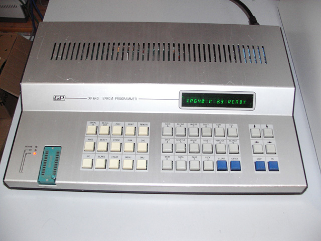
This XP640 was obtained from Ebay and, once again, was working fine until it died without warning and the fluorescent display was blank. After opening the case I found that the PCB mounted sealed transformer was very hot which lead me to believe that it was yet another power supply failure caused by old capacitors. After removing the capacitors they were found to have been manufactured in 1984, very leaky and their capacitance, when measured on a meter, was changing all the time. The marked values were as follows
with some changes required because of component availability.
After replacing all the capacitors and powering on, the voltages on the PCB seemed correct but the display was still blank. The voltages are brought out to a male 6 pin Molex connector near to the VFD
and, numbering from left to right, are
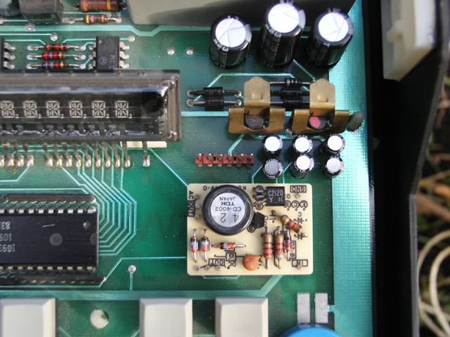
The filament voltage, measured across the end pins of the VFD, was less than 1V AC which was not high enough to create a display. There is a TDK CD-4002 voltage regulator on the PCB to generate the filament voltage and -26V, -19V & -10V for anodes and grids and I removed it to test. It uses a +5V supply to generate these outputs and when driving a resistance similar to the filament the output was much higher, very strange.
I vaguely remembered that it should beep on power up which it now did not so I turned my attention to the Z80A CPU and, using a logic analyser, tried to check that it was running correctly. However, it seemed to be stuck in a loop and did not execute the program as it should. I had a dump of the EPROM contents and used this to check the instructions executed after a reset. The first instruction at address 0000 is "C3 4D 00", a jump to 004D, but I was surprised to see that execution jumped to 004A ! The instruction at address 004A was "C3 99 21", a jump to 2199, but it jumped to a different address instead which proved that the CPU was faulty. Unfortunately, the Z80A was soldered directly to the PCB and to minimise damage to the board I cut the legs and desoldered them individually afterwards. After fitting an IC socket and a replacement CPU, I switched on the XP640, it beeped and the display was working again. But why was the filament voltage so low before ?
By default at power on all outputs of the 10937P VFD driver IC are driven to -10V and I believe that, in these circumstances, the CD-4002 is unable to provide enough power for the driver IC and create the normal filament voltage of 6.36V AC. Also, in this state the CD-4002 must present a considerable load on the +5V supply and my theory is that the CPU failed, the display driver IC was left in a state where outputs were fixed which loaded the +5V supply and caused the transformer to overheat. The age of the capacitors fitted made the situation worse.
It should be noted that there is no fan in the XP640 meaning it is very easy for it to overheat. It is also quite difficult to desolder components on the PCB without pads coming loose so only remove components if you have to.
As a final note I feel that I must draw attention to a couple of interesting points in the design of the XP640.
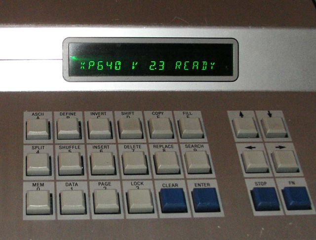
The XP640 started to enter the device menu automatically at power on. Realising that the "Menu" keyswitch was to blame I desoldered it and it measured 1300 ohms across the contacts which was low enough to be seen as a key-press. There was some contamination at the base of the switch possibly caused by a liquid spillage, coffee probably :-).
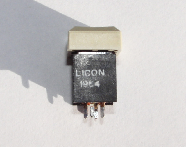
I could find no way to disassemble it without causing damage so I left it in a solution of Propanol overnight. By the next day the switch was working again but, as the "Menu" key is used more than the others, I swapped it with the "Emulator" key and the XP640 was functioning correctly again, see below.